WUXI RUIEN TECHNOLOGY CO.,LTD

Detailed Explanation of Horizontal Machining Centers
Release time:
Jun 05,2025
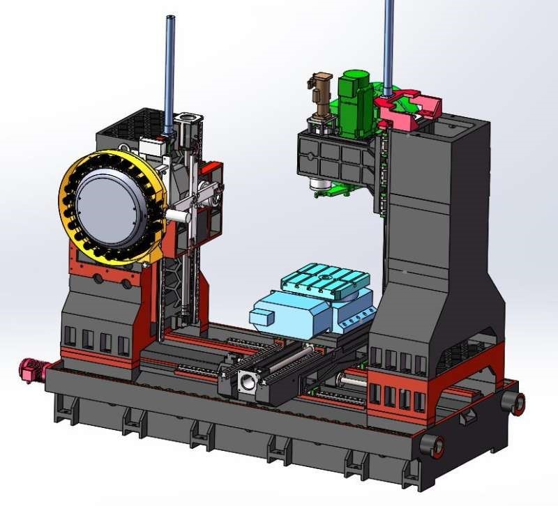
A horizontal machining center refers to a machining center machine tool in which the spindle axis is set parallel to the worktable.
A horizontal machining center refers to a machining center machine tool in which the spindle axis is set parallel to the worktable. It can process larger parts and also perform indexing rotary processing. It is most suitable for multi-process processing such as milling, drilling, boring, reaming, tapping, two-dimensional and three-dimensional curved surfaces of parts with multiple working surfaces. It has excellent performance in completing the box hole system and plane processing in one clamping, and is particularly suitable for the reversing boring processing of box holes. It is widely applied in industries such as automobiles, internal combustion engines, aerospace, home appliances, and general machinery.

Horizontal machining centers are classified into fixed column type and moving column type according to whether the column moves.
Ⅰ. Fixed column type
1. The worktable moves in a cross direction, with the worktable moving in the X and Z directions and the spindle box moving in the Y direction. The spindle box can be hung in two forms on the column: upright hanging and side hanging. It is suitable for multi-process processing such as boring and milling of medium-sized and complex parts.
2. The spindle box moves in a cross direction. The spindle box moves in the X and Z directions, and the worktable moves in the Y direction. It is suitable for multi-process processing such as boring and milling of small and medium-sized parts.
3. The headstock is side-hung with the column, and the headstock moves in the Y and Z directions. This layout is similar to that of the planing table type horizontal milling and boring machine, with the worktable moving in the X direction. It is suitable for multi-process processing such as boring and milling of medium-sized parts.
Ⅱ. Mobile column type
1. Planing type, the bed is in a T shape, the worktable moves in the X direction on the front bed, and the column moves in the Z direction on the rear bed. The spindle box has two forms on the column: upright hanging and side hanging, and moves in the Y direction. It is suitable for medium and large-sized parts, especially for multi-process processing such as boring and milling of parts with longer lengths.
2. The column cross movement type: The column moves in Z and U (parallel to the X direction) directions, the spindle box moves in the Y direction on the column, and the worktable moves in the X direction on the front bed. It is suitable for multi-process processing such as boring and milling of medium-sized and complex parts.
3. Spindle ram feed type: The spindle box moves in the Y direction on the column, and the spindle ram moves in the Z direction. The column moves in the X direction. The workbench is fixed or equipped with a rotary table. It can be equipped with multiple workbenches and is suitable for processing multiple small and medium-sized parts. The loading and unloading of workpieces and the cutting time can overlap.
The difference from vertical machining centers
Ⅰ. Workbench
The worktable of a vertical machining center is generally a T-slot worktable with a cross-slide structure. It has two sets of motion mechanisms responsible for the movement of the worktable in mutually perpendicular directions. The worktable for X-direction feed covers the guide rails responsible for Y-direction feed.
The worktable of a horizontal machining center only moves in the X or Y direction. The form of the worktable is generally a rotary worktable with a dot matrix screw hole table surface, which is relatively easy to be equipped with an exchangeable double worktable.
Ⅱ. Main Shaft
A vertical machining center refers to a machining center with a vertical spindle, while a horizontal machining center refers to a machining center with a horizontal spindle.
Ⅲ. Processing Objects
Vertical machining centers are limited by the height of the column and the tool changing device, and cannot process very tall parts. They are suitable for processing disc, sleeve and plate parts. The volume of the workpieces processed is relatively small. If side processing of the workpiece is to be achieved, an Angle head or a CNC rotary table must be installed. If a rotary table that rotates along a horizontal axis is installed on the workbench, it can be used to process helical parts.
The horizontal machining center can complete the processing of the four surfaces except the installation surface and the top surface after a single clamping. It is most suitable for processing box-type parts. After installing an Angle head, it can achieve five-sided processing.
Ⅳ. Columns
The columns of vertical machining centers generally do not move. To pursue rigidity, they are usually made as thick and strong as possible. There is also a moving column vertical machining center. The worktable of a moving column vertical machining center only moves in the X or Y direction, and the column will correspondingly move in the Y or X direction. This design method has a relatively high power requirement for the drive motor of the column.
The column of a horizontal machining center must be of the moving column type. The column of a positive T-shaped horizontal machining center moves along the X direction, while that of an inverted T-shaped horizontal machining center moves along the Z direction. The structure of the mobile column requires that the column must be as light as possible while meeting the rigidity requirements. Foreign machine tools often use steel plate welded structures to solve this problem.
V. Chip Removal
When a vertical machining center is processing cavities or concave surfaces, the chips are not easy to be discharged. In severe cases, it may damage the cutting tool, destroy the machined surface and affect the smooth progress of the processing.
When processing with a horizontal machining center, chip removal is easy and the processing condition is relatively ideal.
Ⅵ. Control
The vertical machining center is easy to clamp, convenient to operate, easy to observe the processing situation, and easy to debug the program.
The workpieces processed by horizontal machining centers are generally large in size, difficult to clamp, hard to monitor the processing process, and relatively difficult to operate and debug.

Related News
Our company looks forward to becoming your loyal friend and partner, and is willing to work together with you to create a better future!

WUXI RUIEN TECHNOLOGY
Add: #17 Building, No. 288 Hubin Road, Helian Industrial Park, Wuxi ,Jiangsu Province China, 214100
CEO Linda Zhang
Cellphone/Wechat: 0086 13033515883
Email: linda.zhang@ruien-hitech.com


Online Message
If you have any product related questions, please feel free to contact us!
Engine Parts, Fuel Injection System, Auto Filter, Automotive Electronics System